HowTo: Single-Plane Rotor Balancing with Single-Channel Four-Run Method
Rotor imbalance is the uneven distribution of mass on a rotor, leading to the misalignment of the center of mass of the rotor with the center of rotation of the rotor. It is a common cause of rotor vibration and noise, resulting in the reduction of machine life and increase in maintenance costs in the long run. Rotor imbalance can be reduced by adding or removing weights at proper positions on the rotor in the rotor balancing process.
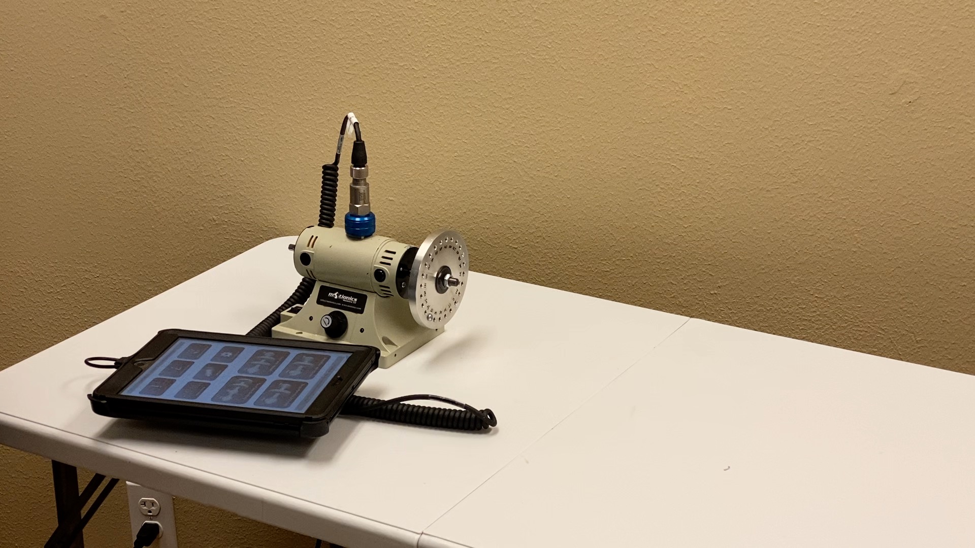
The single-channel four-run method is a commonly used method for single-plane rotor balancing. It only requires vibration amplitudes calculated from accelerometer vibration signals, eliminating the need to use an additional laser tachometer for phase angle measurement. The setup of using Motionics iPad 2CH Vibration Analysis & Rotor Balancing Kit for data collection is shown in Figure 1.

Figure 1 Single-Channel Four-Run Balancing Setup
The procedures of single-channel four-run method are summarized below:
a) Take original vibration.
b) Add a trial weight to 0° on the rotor and take vibration with trial weight.
c) Move the same trial weight to 120° and take vibration with trial weight.
d) Move the same trial weight to 240° and take vibration with trial weight.
Table 1 records a set of vibration readings from a four-run balancing process on a small rotor.
| Trial Weight | 1.63 g |
| Run 1: Original Vibration | 0.4852 ips |
| Run 2: Vibration w/ Trial Weight at 0° | 0.6759 ips |
| Run 3: Vibration w/ Trial Weight at 120° | 0.7595 ips |
| Run 4: Vibration w/ Trial Weight at 240° | 0.2045 ips |
Table 1 Single-Channel Four-Run Balancing Parameters
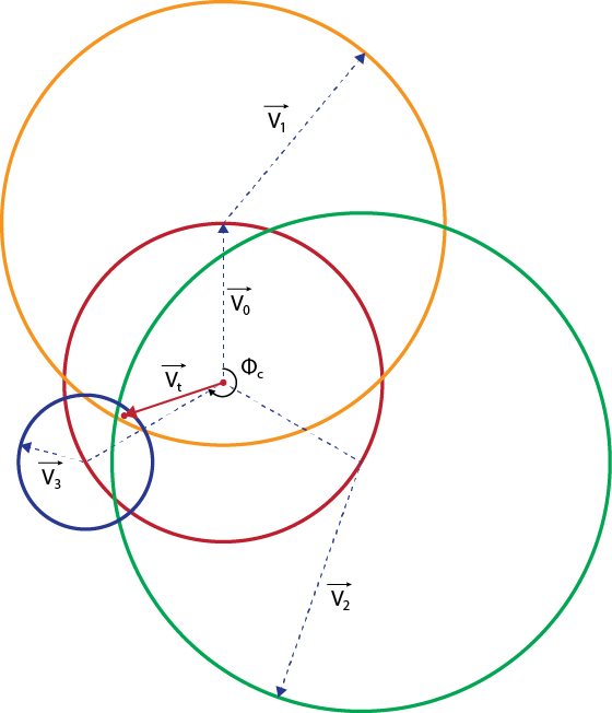
In order to calculate the proper correction weight, a graphic method can be used (illustrated in Figure 2):
a) Draw a base circle using the original vibration V0 (0.4852) as the radius
b) At 0° on the base circle, draw a circle using the run 2 vibration V1 (0.6759) as the radius
c) At 120° on the base circle, draw a circle using the run 3 vibration V2 (0.7595) as the radius
d) At 240° on the base circle, draw a circle using the run 4 vibration V3 (0.2045) as the radius
e) Roughly mark the center of the intersection, connect with the base circle center point, measure Vt length (0.3337) and angle ∅𝑐 (252°)
f) The correction weight value can be calculated as |𝑉0|∗𝑊𝑡/|𝑉𝑡| (2.37), angle equals to ∅𝑐 (252°)

Figure 2 Single Plane Four-Run Balancing Diagram
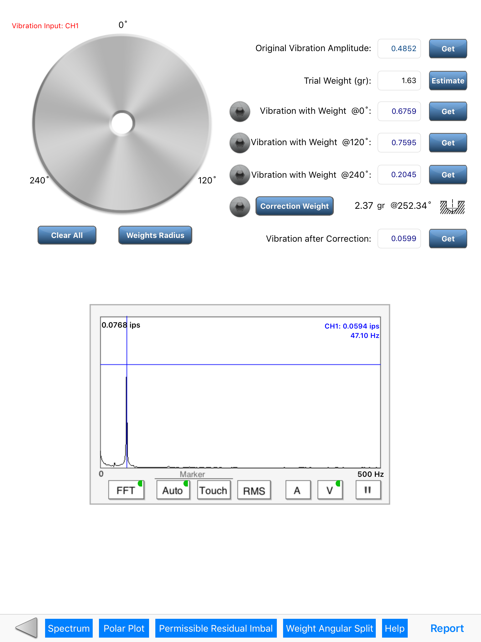
The whole process can also be completed in Motionics iRotorBalancer iPad App with a few taps. On the FourRun balancing page, four vibration runs are listed in order and four Get buttons are added for the user to capture vibration in each run. After four vibration readings have been taken, the user only needs to press the Correction Weight button to get the correction weight.

Figure 3 Single-Plane Four-Run Balancing using iRotorBalancer App