How to Measure Crankshaft Deflection
What is Crankshaft Deflection?
Crankshaft deflection happens after some time, amid the repeated and constant utilization of the crankshaft.
It is a procedure that happens out of sight as the motor works, and, although it can’t be seen without a detection instrument, it causes huge harm to the component.
Without correcting the movements in the crankshaft, after some time, the machine will wear unevenly, causing undue weight on the supporting segments.
This will diminish the valuable lifetime of the motor, making it wear out rashly. This commonly occurring issue can be effectively corrected with minor alterations.


Image reference: http://s7d2.scene7.com/is/content/Caterpillar/CM20160713-53120-62927
The Need to Measure Deflection:
A crankshaft comprises of crank-webs, crank pins and journals along its length. The weight of the crankshaft is upheld by the main bearings at the journals.
Over some time as the motor continues running, the wear in the bearings may not be uniform across the whole length of the crankshaft.
This implies the crankshaft won’t stay in the underlying straight line and will get bent either upward or downward to a slight degree which may not be noticeable to the naked eye, but could be enough to cause hazardous levels of fatigue in the crank webs. This is why there is need of
measuring crankshaft deflections at regular intervals to guarantee that the alignment of the shaft is within secure and permitted limits.
How to take Crankshaft Deflections?

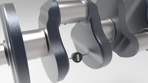
The figure above gives an idea of which measurement is taken to discover the deflection of the crankshaft. As can be seen in the above image, a dial
gauge is placed between the crank-webs to discover the distance between them. If the deflection is measured after a specific time interval, it must be taken at the exact same point, otherwise the reading won’t give a genuine reflection of the level of deflection.
Typically a center punch is utilized to make markings with the goal that each time the deflection is taken at a similar point. Preferably, the deflection should be taken at four points of the crank, namely top, bottom and each side.

Aside from using the exact same point on the crank-webs for measuring deflection, there are different factors which should be remembered, including incorporate load on the motor, trim, hog, sag etc.
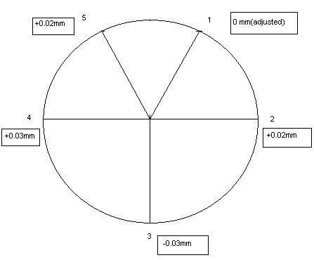
In genuine practice, the bottom reading isn’t taken because of risks of fouling by the connecting rod, so readings are taken on both sides
of the bottom position, and in total 5 readings are taken from each crank-web at the positions appeared in the figure below.

Image reference: https://hfoplant.blogspot.com/2011/07/tc.html